
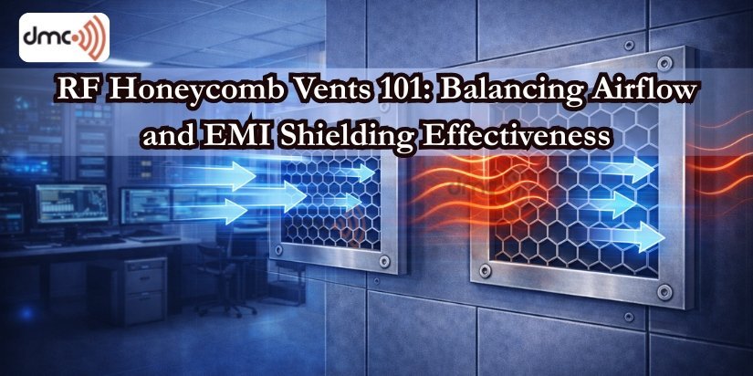
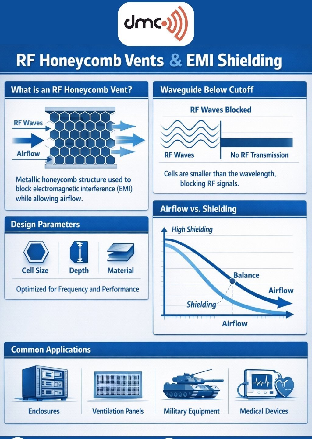
An RF honeycomb vent is an EMI-shielded ventilation panel: a block of conductive hexagonal (or square) cells that lets cooling air pass while blocking electromagnetic waves. The cells are typically aluminum, steel, or a plated metal, and together they attenuate RF and microwave energy at the wall of a shielded enclosure without choking off airflow.
Why ventilation matters in a shielded enclosure
Sealed shielded rooms and enclosures trap the heat thrown off by RF transmitters, test instruments, servers, and power supplies. Left unventilated, that heat buildup leads to equipment failure, inaccurate test results, and shortened service life. A honeycomb vent opens a controlled path for air while keeping the shield continuous.
How the honeycomb blocks EMI
The physics is waveguide-below-cutoff. Each cell behaves like a tiny waveguide, and when the cell is small relative to the wavelength of an incident signal, that signal is attenuated instead of passing through. Air molecules move freely; electromagnetic energy does not.
The design parameters that set performance
- Cell size — smaller cells shield better, especially at higher frequencies, but restrict airflow and raise pressure drop. Larger cells flow more air and shield less.
- Vent depth — a thicker vent attenuates more, at the cost of airflow resistance and price.
- Material and finish — aluminum, steel, copper- or nickel-plated; higher conductivity means stronger shielding.
- Open-area ratio — the share of the face that is open air sets the trade between ventilation and shielding.
Shielding vs. airflow: the core trade-off
Shielding effectiveness for these vents typically ranges from 60 dB to 120 dB depending on frequency, and almost any gain in shielding costs you airflow. Where natural ventilation isn't enough, forced-air cooling is added to make up the difference. The right vent is the one that meets the shielding spec with the least pressure drop your cooling design can live with.
Where they're used
- Anechoic chambers for antenna and RF testing
- EMI/EMC test laboratories
- Data centers and server rooms
- Defense and aerospace facilities
- Medical imaging rooms (MRI, CT)
- Telecom shelters, shielded racks, and cabinets
Installation best practices
- Maintain continuous electrical bonding to the enclosure wall.
- Avoid gaps and non-conductive mounting hardware.
- Use EMI gaskets at the frame where needed.
- Align the airflow direction with the cooling system design.
Done poorly, the vent becomes the weak point in the shield. Done well, it disappears into the wall's performance.
Testing and standards
Vents are evaluated for shielding effectiveness across frequency against recognized standards — IEEE 299, MIL-STD-285, and the IEC 61000 series — before they go into service.
Choosing the right vent
- Required shielding effectiveness, in dB
- The frequency range you need to attenuate
- Airflow and cooling requirements
- Environment — humidity, corrosion, vibration
- Applicable standards compliance
Mission-critical installations often call for a custom vent tuned to hit the shielding target at the lowest possible pressure drop. That balance — airflow where you need it, shielding where it counts — is exactly what our EMI ventilation honeycomb is built to deliver.
Adapted from our parent company, DMC RF — read the original.